
Recently the internet noticed the Raspberry Pi could drive LCD panels using DPI. This allows very inexpensive displays to be used with basically no additional hardware. In this post we dive into the hardware required, the software configuration, how to read screen datasheets, and basic troubleshooting.
A quick word of warning, this is an advanced project. The rewards are significant but it’s difficult to get right.
There are no specific prerequisite skills necessary, but a reasonable understanding of Linux and digital signals is extremely helpful.
Disclaimer and thanks
I am not an electrical engineer. This post was my first adventure into display technology. I managed to cobble it together from the wonderful posts on the Raspberry Pi forum. Specifically this post: http://www.raspberrypi.org/forums/viewtopic.php?f=100&t=86658. It’s great reading on it’s own, and most of the information here was derived from it.
Special thanks is due to Gert van Loo @ Fenlogic for this project: https://github.com/fenlogic/vga666 and Dom Cobley @ Broadcom for maintaining the VideoCore firmware, and posting config examples on the Raspberry Pi forum.
Thanks to forum users “Fat D”, and “ceteras” for pointing me in the right direction and generally being awesome.
Additional thanks is due to Shannon Geis for editing this post, and Lady Ada at Adafruit Industries who posted the video that brought this to my attention.
DPI is awesome
The main reason is because it’s wonderfully stupid.
DPI stands for Display Parallel Interface (or possibly Display Pixel Interface depending on who you ask). It allows you to use very cheap displays by driving them manually. The Raspberry Pi supports this but it may not be right for every project.
Pros:
- Very fast, easily driving our display at 60hz.
- No complicated interface hardware.
- Pixel perfect output. Digital, not analog.
- Easy to understand protocol.
- No bulky connectors.
- Very inexpensive.
Cons:
- Eats a lot of GPIO pins (All of them at true color, but more on this later.)
- Not widely adopted on the Raspberry Pi, making online help hard to find.
- Ribbon cables are easy to break if you’re not careful.
- Short range. If you want your screen 10 meters from the Pi use HDMI.
- There will be maths, this isn’t plug-n-play.
- Almost zero official documentation.
Bill of materials
- 40-pin TFT Friend
- 5.0″ 40-pin 800×480 TFT Display without Touchscreen
- Premium Female/Female Jumper Wires – 40 x 6″ (Optional, but great for prototyping.)
Total cost at time of writing is less than $50, putting this into impulse buy/weekend project territory. You can also use the 7-inch screen Adafruit sells or any 40pin DPI screen, but some of the numbers later are probably not going to jive with it. You will have to find your own way there. Similarly, I’m not using touch screens because I’ve never seen a touch interface that wasn’t terrible, and it lowers the cost a bit. If you want to add touch you’re going to need a touch controller, but that’s another blog post.
A quick note on breadboards…
I strongly recommend not using a bread board for this project. Individual pixels are written at speeds in excess of 23MHz for the example screen and possibly faster for larger panels. Due to breadboard capacitance at these frequencies, cross talk between the parallel color bus is significant and very likely to cause problems. For testing make connections as direct as possible.
Tools
You’re probably going to need some diagnostic tools. A multimeter is always great to have around to verify connections, but if you run into any real trouble you’re going to need a way to visualize the display data. I made due with a cheap USB logic analyzer, but an oscilloscope with 4 channels or more would have made my life a lot easier. It’s not impossible to pull this off with out these tools, but you’re going to be doing a lot of guess work and cursing.
Color depth
The Raspberry Pi B+ has 28 GPIO Pins. We will be using them to drive the TFT directly. If we wanted to drive full 24 bit true color we would need 8 pins each for red, green, and blue as well as pins for hsync, vsync, clock, and display enable. This is a grand total of…28 pins. Great news if you don’t need GPIO for any other purposes, but I do. The way around this is to simply omit the two least-significant-bits on each color bus. Giving us 18 bit high color. Obviously we have lost some data but it’s not as bad as one would expect. I’m using this display for console emulation, and most older consoles are running with far less than 18 bit color.
Physical connections
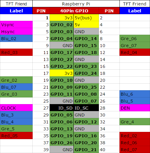
(The original Google Sheet is available here.)
You will notice we need the seldom use pins 27 and 28. These pins are used to detect “Pi hats”, since we need these pins for Clock and DEN, you won’t be able to piggy back a hat on top of this, and converting this to one will be difficult/possibly impossible. Again, because we are using 18 bit color we have gained back 6 GPIO pins, specifically 22-27. If you want to experiment with other configurations with more or less color check out this post on the Raspberry Pi forum and update your device tree accordingly.
Notes on back light drivers
I’m not covering back light drivers here. Mostly because the TFT friend has one built in. It’s actually the only part of the board that isn’t simply a pass through. It uses a 24 volt boost converter that can power a 7 LED backlight with selectable current limits. I *think* it also supports dimming via the PWM line but I haven’t tested it yet. Your mileage may vary.
Device tree
Device trees allow you to reconfigure peripherals on the Pi. Here we use it to enable the DPI interface. It’s a complicated subject and it’s been well documented by the Raspberry Pi foundation. So i’m not going to rewrite the details here. The denlogic/vga666 repo has a copy of the device tree used on the VGA666 board. I’ve trimmed it down to only the B+, and added comments.
You can find it here: https://github.com/robertely/dpi666/blob/master/setup/dt-blob-dpi.dts
If you want to use more or less color pins, or are using it on a different board, fork and modify this file accordingly.
This config needs to be compiled into a blob and placed on the /boot partition. This is easily done with utilities on the Pi, and are in the raspbian repos.
$ cd ~
$ sudo apt-get install device-tree-compiler
$ wget https://raw.githubusercontent.com/robertely/dpi666/master/setup/dt-blob-dpi.dts
$ sudo dtc -I dts -O dtb -o /boot/dt-blob.bin dt-blob-dpi.dts
The data sheet and you
Time to get to know your LCD. Take your time here, there are a lot of details.
If your using the 5-inch Adafruit TFT you may be able to skip this, but you should at least skim it for troubleshooting.
Data sheets should provide you with every thing you need to get hooked up. Unfortunately most of them are written like a bad Chinese/English Google translation dictated over a Walkie Talkie strapped to a wood chipper. There will be mistakes, omissions, nonsense, and–unless you are an electrical engineer–technical details that are way over your head.
Let’s skip ahead a little and look at some of the configurable variables we will need in the config.txt.
dpi_output_format:
| Name | Description | Unit |
| output_format | Complex, see “Additional settings” | Binary(1-7, 4 bits) |
| rgb_order | Complex, see “Additional settings” | Binary(1-4, 4 bits) |
| output_enable_mode | 0: Enable data valid / 1: Combined sync | Binary (1/0) |
| invert_pixel_clock | Invert (0:Stable high / 1:Stable low) | Binary (1/0) |
| hsync_disable | Disable hsync | Binary (1/0) |
| vsync_disable | Disable vsync | Binary (1/0) |
| output_enable_disable | Disable DEN pin | Binary (1/0) |
| hsync_polarity | Invert (0:Normal / 1:Inverted ) | Binary (1/0) |
| vsync_polarity | Invert (0:Normal / 1:Inverted ) | Binary (1/0) |
| output_enable_polarity | Invert (0:Normal / 1:Inverted ) | Binary (1/0) |
| hsync_phase | 0: Rising / 1: Falling edge triggering | Binary (1/0) |
| vsync_phase | 0: Rising / 1: Falling edge triggering | Binary (1/0) |
| output_enable_phase | 0: Rising / 1: Falling edge triggering | Binary (1/0) |
hdmi_timings:
| Name | Description | Unit |
| h_active_pixels | Horizontal Length (Width) | Pixels |
| h_sync_polarity | Invert (Active heigh/active low) | Binary (1/0) |
| h_front_porch | Horizontal forward padding from DEN | Clock Cycles |
| h_sync_pulse | Hsync pulse width | Clock Cycles |
| h_back_porch | Vertical back padding from DEN | Clock Cycles |
| v_active_lines | Vertical Length (Height) | Pixels |
| v_sync_polarity | Invert (Active high/Active low) | Binary (1/0) |
| v_front_porch | Vertical forward padding from DEN | Clock Cycles |
| v_sync_pulse | Vsync pulse width | Clock Cycles |
| v_back_porch | Vertical back padding from DEN | Clock Cycles |
| v_sync_offset_a | Unknown, left at zero | |
| v_sync_offset_b | Unknown, left at zero | |
| pixel_rep | Unknown, left at zero | |
| frame_rate | Screen refresh rate(typically 50-60) | Hz |
| interlaces | Flicker reduction | Frames |
| pixel_freq | Clock frequency (Width*Height*Frame rate) | Hz |
| aspect_ratio | Complex, see “Additional settings” |
Don’t be afraid. This is a pretty significant list of confusing options, but the data sheet will provide most of the unknowns. For the rest, we will leave them at defaults or educated guesses, honed with trial and error.
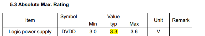
I found my data sheet by searching for the part number: KD50G21-40NT-A1* (PDF LINK.) This was found on an official looking sticker, but a number of other serial numbers and seemingly random strings were also there.
Looking it over, the first bits of useful information are found on page 7 Fig 5.2/5.3 . Here we find resolution, and voltage information. The most important is confirmation that the logic voltage is 3.3v. This allows us to drive the LCD with out a level shiftier:
Page 10 Fig. 5.6/5.7 gives us a pinout of the ribbon cable and led driver information:

Page 14 Fig. 6.2.3 gives us a lot of data on timings. These are pretty impossible to figure out with out documentation.
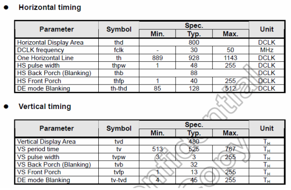
Additionally, you’re going to find a lot of diagrams showing what the display output looks like, these are going to be pretty meaningless with out a scope or logic analyzer.
*This pdf was found hosted on adafruit.com, but not linked on the screen sales page. I don’t know why.
Additional settings
Lets now look at three settings you didn’t see in the data sheet. Consult the following tables for output_format, rgb_order, and aspect_ratio.
output_format:
| 1 | DPI_OUTPUT_FORMAT_9BIT_666 |
| 2 | DPI_OUTPUT_FORMAT_16BIT_565_CFG1 |
| 3 | DPI_OUTPUT_FORMAT_16BIT_565_CFG2 |
| 4 | DPI_OUTPUT_FORMAT_16BIT_565_CFG3 |
| 5 | DPI_OUTPUT_FORMAT_18BIT_666_CFG1 |
| 6 | DPI_OUTPUT_FORMAT_18BIT_666_CFG2 |
| 7 | DPI_OUTPUT_FORMAT_24BIT_888 |
We will be using option 6 for 18 bit color, CFG1. I don’t for the life of me know what CFG1 is, but CFG2 didn’t work (trial and error.)
rgb_order:
| 1 | DPI_RGB_ORDER_RGB |
| 2 | DPI_RGB_ORDER_BGR |
| 3 | DPI_RGB_ORDER_GRB |
| 4 | DPI_RGB_ORDER_BRG |
Option 1 here is fine unless you wanted to get creative with your wiring.
aspect_ratio:
| 1 | HDMI_ASPECT_4_3 |
| 2 | HDMI_ASPECT_14_9 |
| 3 | HDMI_ASPECT_16_9 |
| 4 | HDMI_ASPECT_5_4 |
| 5 | HDMI_ASPECT_16_10 |
| 6 | HDMI_ASPECT_15_9 |
| 7 | HDMI_ASPECT_21_9 |
| 8 | HDMI_ASPECT_64_27 |
While not exactly correct I use option 6 with the best results.
/boot/config.txt
Every thing above has to be added to the config.txt and only in 2 lines:
dpi_output_format=458773
hdmi_timings=800 1 0 48 0 480 0 13 3 32 0 0 0 60 0 23040000 6
Points lost for readability, but the data is there.
dpi_output is a uint32 representation of all the binary values in the dpi_output table above.
hdmi_timings is a space delimited list of the hdmi_timings table above.
Rewriting these by hand became very old, very quickly. So I’ve created a spreadsheet to aid those trying to do the same.
It can be downloaded here, or viewed live in Google Sheets here.
The rest of the options are comparatively trivial:
###
# For use with the adafruit 5' tft only.
##

#Overscan Information.
overscan_left=-32
overscan_right=-32
overscan_top=-32
overscan_bottom=-32
framebuffer_width=800
framebuffer_height=480

# Disable spi and i2c, we need these pins.
dtparam=spi=off
dtparam=i2c_arm=off

#Enable the lcd, enable custom display sizes with CVT, set as the default output.
enable_dpi_lcd=1
dpi_group=2
dpi_mode=87 # Hdmi CVT
display_default_lcd=1

dpi_output_format=458773
hdmi_timings=800 1 0 48 0 480 0 13 3 32 0 0 0 60 0 23040000 6
With these changes you should be able to reboot and get some kind of picture.
Testing the frame buffer
At first, the best way to test is with images, I used these in testing:


To display these images directly to the frame buffer with out all the fuss involved with X, use a utility called fbi.
$ cd ~
$ sudo apt-get install fbi
$ wget http://blog.reasonablycorrect.com/wp-content/uploads/2015/03/colorbars.gif
$ sudo fbi -T 1 colorbars.gif
The “-T 1” lets you run the utility over ssh. I didn’t have a keyboard attached for most of my work.
Once you are confident you have color down you may want to test acceleration. HD video with omxplayer is the fastest way. Big Buck Bunny is a free as in beer open source video available in a variety of formats and sizes.
$ cd ~
$ wget https://archive.org/download/BigBuckBunny_328/BigBuckBunny_512kb.mp4
$ sudo apt-get update
$ sudo apt-get install omxplayer
$ omxplayer BigBuckBunny_512kb.mp4
*As a side note that kitten looks horrifying with just red connected.
Troubleshooting
My first attempt at this was on a bread board. I lost an entire afternoon to this because of cross talk on the color lines and my inability to recognize it.
Here is an ideal color bar test image:

Here is what I was seeing(The smudge is from a screen protector.):
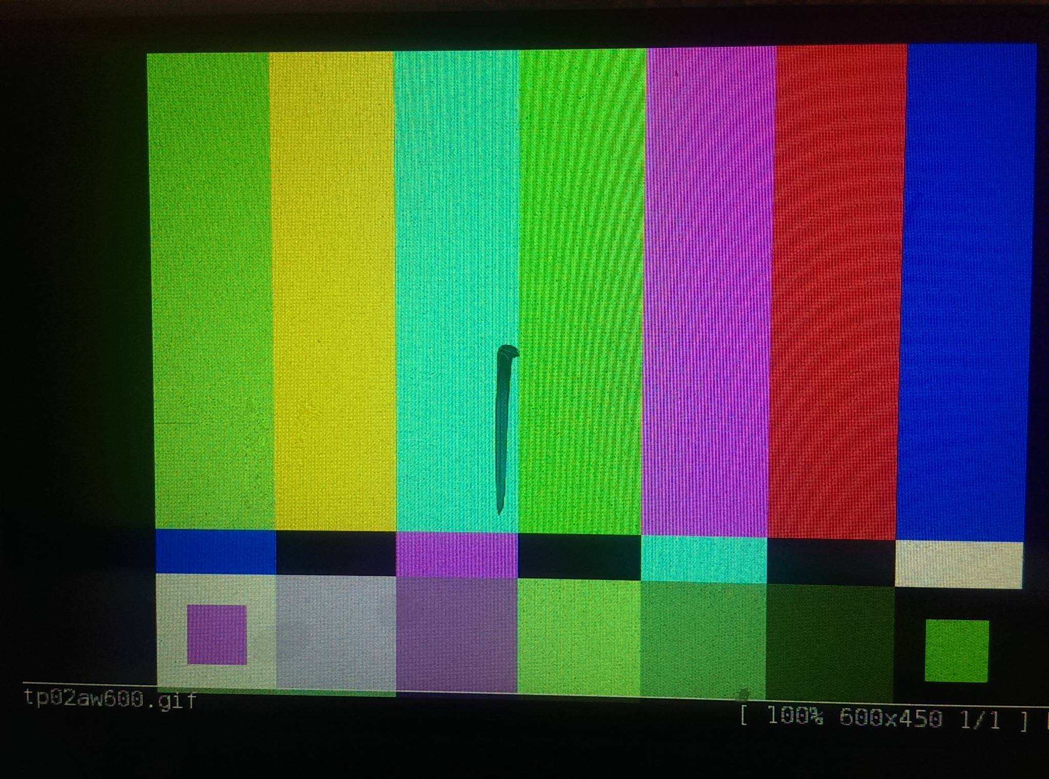
As you can see It manifests in a really interesting way. Color extremes will look perfectly normal. for instance pure red, or #FF0000 in hex will look fine, but #CC0000 will look “weird”
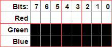
Lets visualize what the bus state will be showing those colors in a perfect world:
Black boxes “off” or logical zero, and white boxes “on” or logical one
#FF0000
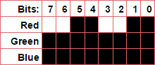
#CC0000
Now lets look at what #CC0000 could look like in the real world with cross talk:
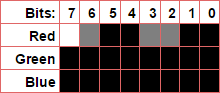
Are pins 6, 3, or 2 On or Off? The screen doesn’t know either.
Capacitance from the breadboard allowed current to seep into the adjacent lines. With out a way to visualize this I would have torn my hair out trying to figuring it out.
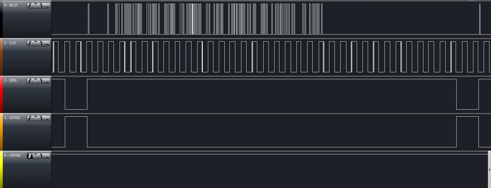
Once I setup my logic analyzer there was obvious something was up. This image represents one horizontal line. The top trace shows the signal on the 7th and most significant bit of the blue bus. It should line up perfectly with the falling edge of the clock pulse but it’s all over the place.
Wrapping up
It took me a while to get every thing working, but that was mostly because there was a serious lack of documentation. Besides getting a cheap screen working I gained a pile of knowledge on display technologies and the inner workings of the Raspberry Pi. I wrote this partially because it helped me commit my findings to memory, but mostly because I wanted it documented for others. I hope you get as much out of this article as I did writing it.
TL;DR
If you’re feeling brave/stupid: Download this, and this. Wire it like this, reboot, and hope.
Edit: 3/5/15, Extended thanks section to include Dom
So we still can’t use the native DSI connector of the raspberry pi, even 3 years later?
Awesome project! I like the stand for the screen ( would be great for a tablet as well). Any more info on what it’s made of / where can I get one?
Hey Abe, it’s totally just a wire hanger bent up.
Unless you live here you you probably have one lying around.
Very cool! I work with an embedded tech company that is actually working on producing some cost effective versions of LCD touchscreens for Pi’s and other SBC’s. It’s largely targeted towards industrial customers for volume, but I’m interested in getting it into the hands of hackers and makers to see what they can do with it.
I recently donated one to a local hacker group in our town, they were able to put together a home automation demo with it, I’d be curious to see what you guys think:
https://www.youtube.com/watch?v=m-ucSp8yfxY
Hey Daniel,
What is your company called?
Ten
Hi, is there any specific reason to use GPIO 2&3 (I2C) for Vsync & Hsync? I’d like to use I2C for some other peripherals, most likely touscreen controller…
Iam creating my own board for 50-Pin 5″ display module from old GPS…
Yes, AFIK you can’t change those pins, but the screen I used does not require h/vsync so you could omit them.
RYU, have you made any progress on this? I would also like to drive some peripherals with I2C.
Totally possible, If you can dump the h/v sync lines (not every display will tolerate this, but the one adafruit sells does.) You can still use the I2c bus. I have one setup with a RTC and DPI screen.
Here is my hot wired Adadfruit “Kippah” with the i2c and power lines broken out: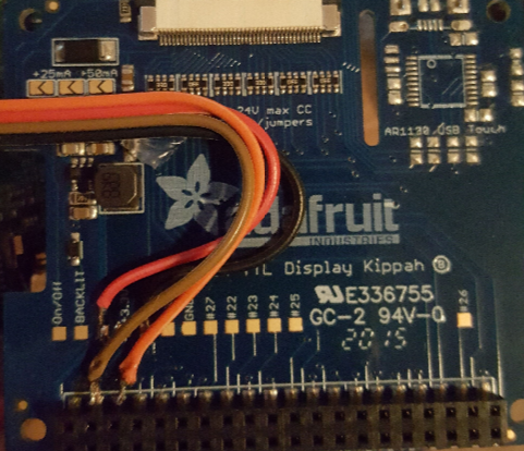
good fun. Sadly, if you spend a little while on ebay you will be able to find pretty good (liquidation stock) 18″ HDMI screens for less than £20
That is certainly true. However the exercise was more to explore the DPI interface, allowing the use of commodity or reclaimed panels.
if you want to get pretty colors, you must use most significant bits
R2…R7
G2…G7
B2…B7
pins R1R0G1G0B1B0 you must connect with positive voltage
you get colors from #070707(mostly black) to #ffffff(white)
I’m not sure but aren’t there any shift registers that could handle those frequencies? That way you could reduce the amount of blocked GPIO pins – especially concerning colour. If you insert a shift register for each colour with each 8 bit they could all share a clock signal, use the same 5V power pin and could also use the same latch signal. That way you could get along with only 1 pin per channel + clock + latch + 5V + Ground. Even if 8 bit shift registers were to big due to clock restrictions (5min research gave me 8bit registers with a max clock of up to 36MHz) and GPIO restrictions (how fast are those GPIO pins actually? I assume it can’t top 16MHz per pin under ideal cpu loads and only by using a fast and compiled language). Even if you rely on those 16MHz, you could still go with 2bits per shift register (if you find one, you could still go with a 4bit register and connect output 3 and 4 to ground with a resistor only using the first two) so you could get along with 4 pins per channel + 1 clock + 1 latch + 5V + Ground = 14 pins + shared 5V + shared ground. Still less than the 18 pins you used in your direct design.
I’m not an electronics expert so maybe I’ve missed something, but I think it would be worth a try.
I haven’t looked it up, but i’m sure there are shift registers capable of this. The problem is you couldn’t drive them from the GFX accelerator peripheral on the Broadcom chip. Since it’s hardwired into a parallel interface.
It would take a low level redesign of the silicone to allow this. At that point you would want to use the DSI (Display Serial Interface) the chip set also supports. So why didn’t we here? Because using it requires a closed source binary blob driver that isn’t out in the wild. Why is that? You would have to ask broadcom, but you would need to buy 10,000 chips and sign away your first born to am NDA from hell to even get talking about such things.
Hi !
So, I have been following each step of your project. But I don’t understand how the link between the config file and the .bin is done. How does the command “enable_dpi_lcd=1” is recognized and used by the Pi ? same with “dpi_output_format” and “hdmi_timings”. I get their purpose and how set them, but I miss the link with the dt-blob-dpi.dts and how to use it… Could you explain me a little bit ?
Thanks in advance 🙂
The firmware changed slightly back in June and altered the format of the dt-blob file slightly. I created a pull request for you on github to make it work again, but you haven’t merged it. Anyone following your instructions on a recent firmware will therefore find it doesn’t work! Adafruit did update the blob in their tutorial for their Kippah DPI interface.
Just as a heads up, something else has cropped up that results in DPI not working. A fix is in progress, but may require either a further blob change, or switching to using a device tree overlay – https://github.com/raspberrypi/linux/issues/1144
Sorry for not merging the request earlier. I really need to setup a better filter for those emails. I need to update this article with a few other changes like rpi2 support, and using I^2c with screens that don’t need h/v syncs. Neither is complicated I just hasn’t had time lately.
And yea, I really hope they have the format nailed down now. DPI support has not been a priority at all, and i’m not entirely sure why.
Thanks for the pull request!
There should be no changes needed for Pi2 support as I added those sections back into the blob that you’ve now merged. That’s actually what I’m running with.
I2C should just work if you load the relevant dt overlay – the kernel will then alter the pin muxing, and if your screen does need those pins it will then go blank!
The base platform names shouldn’t change again, but it still poses an issue as they add new platforms. Ideally the firmware would support merging the base blob with a user supplied section (same as the kernel with overlays), but that isn’t as straightforward as it seems (I leave that bit to Dom and Phil). As mentioned on the github issue, I’m trying to sort out a kernel dtoverlay to do the pin setup – currently not working for a reason I don’t understand. You lose the initial rainbow screen as that is set up before the kernel boots, but that’s not the end of the world.
DPI won’t be a high priority as it steals almost all the GPIOs. They now have the official DSI display which retains all the GPIOs, but that does restrict you to that one panel. There is a concerted effort not to break things that have been released, but it doesn’t always go to plan :-/
I had the same problem using the vga666 board. The latest firmware breaks it. Someone on the forum mentioned that you need both dt-blob.bin and vga666-overlay.dtb loaded to make it work.
This holds true for this project as well. Of course dt-blob and vga666 need a bit of modification to get gpio 0 and 1 enabled in DPI mode. I’ve done it and it works with this LCD: https://hackaday.io/project/10127-palmpi
Hi Robert,
First, thanks for a very detailed writeup on the DPI interface on RaspPi. It was really easy to follow and get the DPI interface up and running on my board.
Where did you get the documentation for dpi_output_format and how it’s used? I need an active-low DEN, but changing that one bit in dpi_output_format did not make DEN active low. It seems that changing the HSYNC or VSYNC polarity in dpi_output_format doesn’t have any effect (but changing them in hdmi_timings does). Unfortunately, there is no DEN polarity flag in hdmi_timings.
Is there an online source that describes the DPI interface on the BCM2835?
Thanks,
Ag Primatic
Another option for cheap screens, old digital picture frames.
These typically break because some stupid phool connected them to the wrong power supply.
Or the backlight controller/tube goes bad, have seen this a few times too.
A good protip, rip open a Philips “40W” 4 strip type LED bulb or simply buy the emitter strips on greedbay.
its possible to actually make a replacement strip tube which fits where the old one used to go and emits enough light @ 10mA 28V or less to make driving it with a single MC34063 chip feasible.
The added advantage is that broken LED bulbs can thus be recycled and avoid wasting the $$$ emitters.
I was successfully get it work based on your instruction for 800×600 lcd.
But when I have try to do the same with my 480×272 screen. But I cannot get anything on screen..
I put dot clk on scope it struct at 25MHz.. No matter what config I am trying to change to. Do you know any command which can I use to change it?
This is one awesome post.Thanks Again.
Hello Robert,
first of all congratulations for the work you did to use economic parallels rgb display.
I’m trying to make it work on a rpi 3 b.
I did a big job for the hardware interface rpi, and now I’m having problems with the software.
The rpi is equipped with ubuntu mate and I don’t have very clear how to use the dtb you’ve created (dt-blob.bin)
I have to merge it with bcm2710-rpi-3-b.dts and add the information for DPI port and recompile it?
Thanks so much,
Nicola
Are there enough details in this Samsung datasheet in order to start playing with this spare TFT Friend ?
http://www.beyondinfinite.com/lcd/Library/Samsung/LTN170X2-L02.pdf
– couldn’t figure out many of the variables that I need to calculate the config options…
Thanks in advance !
The is great stuff, but it makes my built-in audio come out sounding frequency-shifted by about a factor of 22/18 (1.2). I can manually modify the sampling rate for audio commands, but that’s about as ugly as it gets. Any ideas?
Hi Robert,
This is an excellent post. Thank you very much.
I would like to use this VGA interface but I would like to use Red Bear’s IoT pHAT as well with Raspberry Zero. And this is the problem: their pins do not fit together.
I have another idea to add a VGA interface to the Raspberry Pi and I would like to know what is your opinion about it. In the original VGA666 there are 18 pins used to output the three color components plus HSYN and VSYN, in total of 20 pins. My idea is to multiplex the color components on only 6 (or 8) pins and to add a clock output with twice of pixel clock.There is – of course – an additional FPLD integrated circuit on the board. The output of the FPLD feeds the D/A converter built with the resistor ladder. The FPLD contains five 6 (or 8) bit latches: two for red and green components and one for the blue. The two latches of the red and green components are connected in serial thus forming a two-stage chain. The first rising edge of the clock writes the red component into the input latch of the red chain, the first falling edge writes the green component into the input latch of the green chain, the second rising edge writes the blue component into the blue latch and in the same moment it transfers the red and green component from the first latch into the second one. Thus the three color components of a pixel are fed in the same moment into the input of the D/A converter.
The advantages of this solution are:
1. pixels are sharp
2. uses less pins than the original version.
This solution needs that red, green and blue pixel components be multiplexed inside the GPU onto the same GPIO pins and a double pixel frequency be provided from the GPU. And this is the point where I do not have enough knowledge. Is this possible to get with the device tree?
Could you tell me your opinion, please?
Best regards,
Aromo
Hello, very nice and clear writing, just on the way to do it also. I have though one question about the touch, how should I connect it I need the touch functionality on the screen
If your screen has a touch controller (a resistive touch controller) there will be 4 pins referenced in your data sheet that need to be routed to a touch controller. Adafruit has some products that build this in.
Hello, Robert!
Wow, the information on this post is overwhelming!
As I’m pretty much a n00b with the Pi, gpios and C, could you help figure out the entries for this tft HAT > http://tinyurl.com/j9jeszc ?
that’s probably not a DPI screen, it looks 12c from a quick glance. Either way it should come with docs to help. (if it is a good seller.)
Hi,
So, I have a sharp LQ038Q5DR01 lcd, and tried to use dpi connection. All looks good except grey scale colors. Tried a lot of configurations but result is the same. Problem is the same as yours,
but I do not use any breadboard, raspberry pi 2 and lcd connected with 20cm(I think) wires.
Here is my images https://goo.gl/photos/KZwVV4gBNXahSyiD7
Could it be that wires are too long ? I dont have shorter to try. What other problems could be ?
Btw, lcd itself is 18bit color, but custom exposed 40pin connector(came with lcd) uses 16bit(rgb 565)
Here is my config.txt
gpu_mem_1024=256
hdmi_ignore_cec_init=1
disable_overscan=1
start_x=1
#dtoverlay=lirc-rpi
disable_splash=0
gpu_mem_256=112
#sdtv_aspect=0
#dtparam=gpio_in_pin=18
gpu_mem_512=144
#dtparam=gpio_out_pin=17
#dtoverlay=spi-bcm2835-overlay
###
# For use with the adafruit 5′ tft only.
##
dtparam=spi=off
dtparam=i2c_arm=off
dtoverlay=dpi24
#overscan_left=0
#overscan_right=0
#overscan_top=0
#overscan_bottom=0
framebuffer_width=320
framebuffer_height=240
#test_mode=1
enable_dpi_lcd=1
display_default_lcd=1
dpi_group=2
dpi_mode=87
dpi_output_format=19
hdmi_timings=320 0 0 0 72 240 0 0 0 5 0 0 0 0 0 3840000 1
That does indeed look like cross talk. It’s going to take some work to debug, shortening the wires may help.